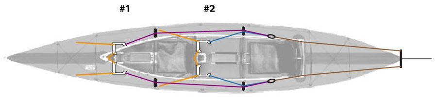
brown: common lines; blue: #1 lines; purple: #2 lines; orange: bungee cord to hold the "boomerang" pedals
Author:
Lutz Pietschker
Version: 2012-07-11
Home Page | Kayaking Main Page | Link Pages | What's New
Wer diese Informationen gerne auf deutsch hätte, schreibt mir bitte eine Mail.
The Greenland II rudder works well enough, but I have two problems with it: There is no provision to let #1 steer, and (as others also have remarked) the pedal assembly is flimsy and not too ergonomic. I decided to build new pedal assemblies for both seats that would allow to steer from either the #1 or #2 seat. This would mean adding a second line to each side, and I changed the pedals to so-called "boomerang" or "stirrup" pedals that are held in place by bungee cord. I made the lines detachable in case only one was needed (see line schema, below, the ellipse where the lines split is a small carbine hook).
brown: common lines; blue: #1 lines; purple: #2 lines; orange: bungee cord to hold the "boomerang" pedals
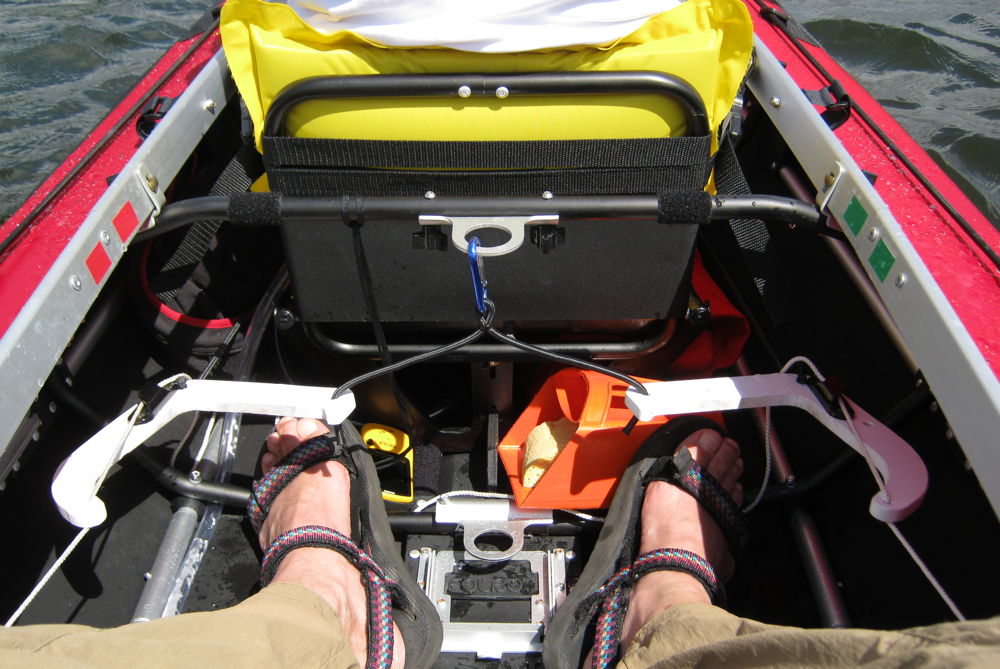
I made the pedals from 10 mm plastic and attached clamcleats to fasten the steering lines. The pedals are held in place by a balance of forces from bungee cords securing them upward and pulling them towards the bow and the steering lines pulling them towards the stern. You need to balance cord lengths and steering line tension to get the pedals where you need them. I used plastic cable ties as stoppers for the bungee cords where they pass through the pedals; they make it very easy to experiment with different lengths until you settle for your best fit.
A nice feature of this kind of steering assembly is that the bungee cord automatically returns it to a center position when you take your feet off the pedals. By putting more or less tension on the steering lines you can also trim the neutral position of the rudder which may be handy on long legs with constant side wind. However, be very careful not to use this trimming option to compensate for uneven paddle strokes (if one of your arms is stronger than the other), you would just confirm and cement a bad habit.
The assembly is very light and takes up very little space in the transport bags. The downside is that the bungee cords may interfere with baggage you want to stow near the seats.
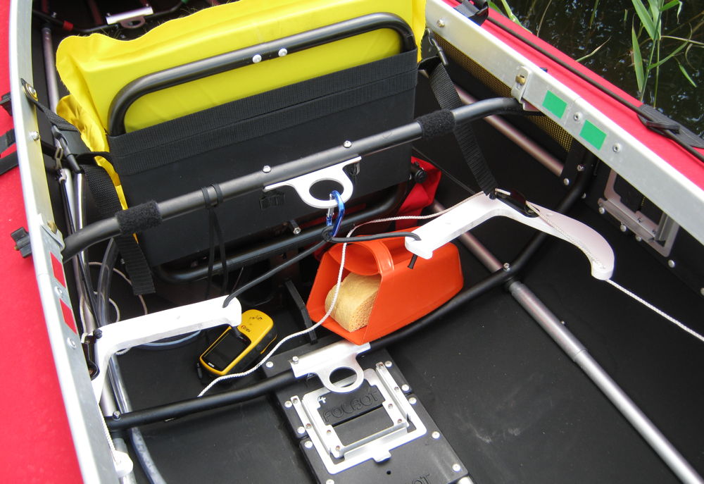
Bungee cord holds the pedals in place; on the left side you see how the cord is attached to the #3 frame.
Next step: I need to add some foot rests, I think.
As the author of this page I take no expressed or implied responsibility for the content of external links; opinions expressed on such pages are not necessarily mine. The web space provider is not responsible for the contents of this page or any linked pages.
Written and published by Lutz Pietschker. Please send comments about technical problems to the
site master.
-Made with a Mac!-
, last change 2011-03-12